


How the OSI Model & Network Communication Layers Work

 (56 votes, average: 4.86 out of 5)
The internet isn’t an abstract idea but has real physical existence. Let’s explore how computers and other devices communicate via networks…
Not so long ago, sending messages to someone living on a different continent required significantly more effort than rolling out of bed and hitting send on your email client. Today, it’s possible to communicate almost instantaneously with our coworkers and buddies. But how exactly does data travel from your colleague’s laptop or your friend’s phone to your device? This is where the OSI model comes into play.
The OSI model and network communications are all about the layers.
What Is the OSI Model?
The Open Systems Interconnection Model (or OSI model) is a framework given to us by the International Organization for Standardization (ISO). Its purpose? To standardize communication protocols and agree on network standards for multi-vendor interoperability. In other words, it enables various devices manufactured by different vendors to communicate in a uniform way. It also serves as a way for people to break down different parts of network systems based on their functions for network communications.
Network Layers: OSI Model vs TCP/IP
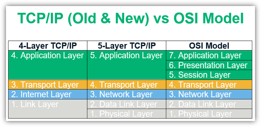
Besides the OSI model, the TCP/IP reference model with its four layers is also used as an industry standard. Now, you may be wondering, isn’t the OSI model the same thing as the TCP/IP model? Yes and no. They’re related but still separate.
TCP/IP, which stands for transmission control protocol/internet protocol, is a protocol suite that traditionally consists of four layers — application, transport, internet, and link. Layers 5, 6, and 7 of the OSI model are mapped to the TCP/IP model’s application layer. The OSI network layer is referred to as the internet layer in the TCP/IP model. Layer 4 of the OSI model is mapped to the corresponding transport layer, while layers 1 and 2 are clubbed into the TCP/IP model’s network access layer. This suite was created almost a decade before the OSI model came into existence.
Dummies.com really clarifies the difference between the two nicely:
“The OSI Model isn’t itself a networking standard in the same sense that Ethernet and TCP/IP are. Rather, the OSI Model is a framework into which the various networking standards can fit. The OSI Model specifies what aspects of a network’s operation can be addressed by various network standards. So, in a sense, the OSI Model is sort of a standard’s standard.”
Familiarizing yourself with the OSI model network layers helps you understand how telecommunication systems work in a granular sense. This can help you identify or resolve issues facing your network. It also helps you see the bigger picture of how data flows between interconnected devices over a network.
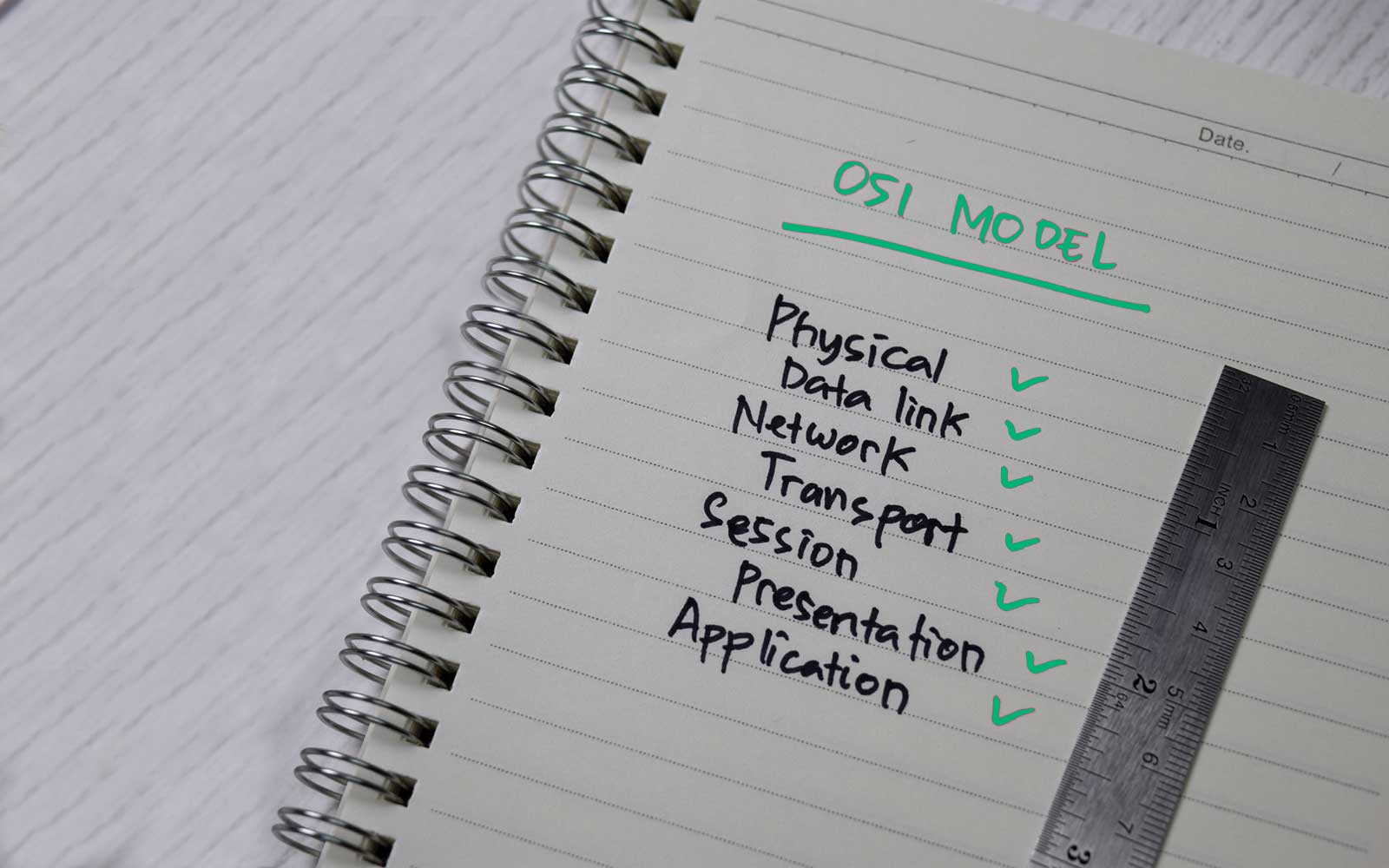
Breaking Down Network Layers: A Look at the 7 OSI Model Layers
The OSI model is more of an interoperability guideline for manufacturers and developers than a strict representation of how the network looks. Instead, it gives an overview of how the data flows across the network. There are seven layers in this model, each with its own set of functionalities and protocol suite. The layers are typically listed in descending order — starting with layer seven and making their way down to layer one.
Let’s consider how this would work in a two-party connection — say, between your computer and a friend’s computer. The seven layers exist on both host devices, and each layer exchanges data with its corresponding counterpart independently of the other layers below. This means that if you send data from your computer to your friend, data on your device’s OSI layer 2 would exchange directly with your friend’s layer 2. Your layer 3 would exchange data with their layer 3, etc.
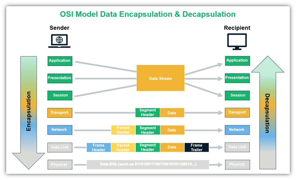
However, there’s one key bit of info we need to touch on. As the data travels down from the application layer of your computer, additional information gets added to the data before it is passed on to the layers below. This process is called data encapsulation because it involves adding protocol information to the beginning (header) and/or end (trailer) of the data.
At the recipient’s end, data decapsulation takes place where the incoming data is unpacked as it moves up the layer till finally, at the application layer, all the additional headers and/or trailers added are stripped off.
Since data moves from the top down when leaving the sender to transmit to the recipient, it seems fitting that we start with seventh layer of the OSI model and work our way down. Let’s explore the OSI model layers!
OSI Layer 7: Application Layer
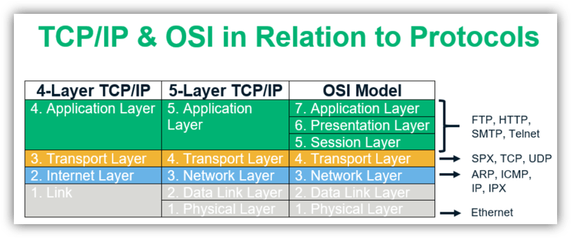
The seventh layer of the OSI model is called the application layer. As the name suggests, it deals with software and applications that run on our computers, such as the web browser you’re using to read this web page. Basically, this layer interacts with end-users through those apps and provides an interface between them and the underlying network connections. Some of the primary protocols used at the application layer are HTTP, DNS, FTP, SMTP, etc.
The application layer forms the human-computer interaction interface that focuses on end-user services. We rely on the application layer whenever we:
- Access or transfer files on a remote machine,
- Store and forward emails,
- Use a virtual terminal, or
- Access directory services.
OSI Layer 6: Presentation Layer
Layer 6 of the OSI model has three primary responsibilities:
- Encoding (for example, ASCII encoding),
- Encryption (like when applying SSL/TLS), and
- Compression (such as by using gzip).
When sending, the data travels from the application to the presentation layer and in the reverse order while receiving.
OSI Layer 5: Session Layer
Session layer, or layer five of the OSI model, deals with session management. Basically, the focus of this layer is on opening, closing, and managing the dialogue that takes place between two parties or endpoints.
Consider the number of applications that a user might have open simultaneously — an email client, a web browser, a text editor, etc. — and how each of those applications may have multiple connections running within them. For example, the web browser could have one tab opened for video, one for email, another for online shopping, and so on. The session layer is tasked with keeping all those connections alive, managing them, and terminating them.
OSI Layer 4: Transport Layer
OSI layer four, known as the transport layer, is responsible for transporting the segments (we’ll look at what segments are in a moment) to the right application or service. Consider an Apache server running in the background listening at port 80 or port 443 for incoming connections. If an incoming message has a destination port as 80, the transport layer will deliver the message to the corresponding service.
The protocol data unit (PDU) at this layer is a segment. The original data is broken up into chunks called segments and sent over multiple pathways to gain some efficiency (by avoiding congestion). It also incorporates security since the segments are scattered and makes it harder for an attacker to read the entire message.
On the receiving device, the transport layer is responsible for reassembling these segments in the correct order before sending it over to the session layer. Each segment contains header information such as source port, assigned based on availability by the client (sender’s) operating system, destination port, sequence and acknowledgment numbers that communicate which segment was delivered and what it expects to receive next. The delivery can either be reliable or unreliable and based on that, the protocols used are TCP or UDP.
In case of a reliable connection (TCP), error control checks are in place that the determine if the message received is complete. If not, it asks the message to be resent. Transmission failures due to differences in connection speeds might occur. Flow control is used so that a sender with a faster connection doesn’t end up overwhelming a receiver with a slow connection. The transport layer also includes multiplexing and demultiplexing to enable clients to communicate with different application processes in one session.
So, what happens in UDP? Let’s take a trip down memory lane and go back to your eighth-grade math class (or any lecture that you can recall). That’s an example of unreliable delivery. Since the teacher delivering the lecture (i.e., the data transmitted) didn’t wait for an acknowledgment from students confirming that the message was delivered in its entirety, it’s a UDP transmission. UDP is used when the size of the file is massive, like in audio or video transmissions, and it is time sensitive. For instance, you wouldn’t want a time lag after every frame in a video.
OSI Layer 3: Network Layer
Layer 3 of the OSI model routes the data along multiple pathways. The PDU for this OSI layer is referred to as a packet. It contains information such as source and destination IP addresses to identify end devices. The most commonly used protocol at this layer is IPv4. The network layer is responsible for:
- Routing packets from source to destination (host-to-host delivery) across different networks,
- Translating logical addresses into physical addresses, and
- Fragmenting packets into smaller pieces to allow it to travel across links with lower maximum transmission units (MTU).
OSI Layer 2: Data Link Layer
The data link layer is layer two of the OSI model and the last layer where encapsulation (frame assembly and disassembly) occurs. It takes the data from the layers above it and links it to the last layer while sending out information. The PDU for the data link layer is called a frame, which is a packet with a header and a trailer. The header signals the beginning of the frame, and the trailer indicates the end of data transmission for a particular frame.
The data link layer has two sublayers:
- Logical Link Control (LLC) layer (the upper sublayer) — The LLC sublayer assists with multiplexing and de-multiplexing over the MAC layer. It takes the packet from the network layer and adds control information to deliver it to right destination (hop-to-hop flow and error control).
- Media Access Control (MAC) layer (the lower sublayer) — The MAC sublayer interacts directly with the physical layer and deals with framing/de-framing, typically done by NIC cards on PCs. It is also responsible for collision resolution on shared or broadcast links where multiple end nodes connect to the same link.
OSI Layer 1: Physical Layer
The first and lowest layer of the OSI model is called the physical layer. It deals with how the devices are physically connected to one another using cables, switches, NICs, etc. and the raw transfer of data via them. Examples include the following to send and receive information:
- Ethernet cables,
- Fiber optic cables,
- Radio signals used in wireless communication, etc. to send or receive information.
Physical layer responsibilities include bit-by-bit-delivery, converting signals from one form to another, line coding, carrier sensing and collision detection, bit synchronization, defining the transmission mode, etc.
How Is the World Connected?
The short answer is via cables. It might be interesting to understand the physical communication channels through which data flows, how they are built, who owns them and gain a general overview of how these channels that connect the entire planet came into existence.
What happens in the background when you’re trying to send an image file to your friend? It gets transformed into 1s and 0s (binary) that are transported using radio waves to the router. This gets done by using frequency modulation where a certain frequency is used to represent 1s and another to signify 0s. So long as the receiver knows which frequency is used to represent the 1s and 0s, they can read the signal.
The information then leaves the router via cables in the form of light or electricity, depending upon the wire’s material. These cables are typically set up and owned by internet service providers (ISPs). The ISPs are responsible for determining the most efficient route that the message can take to reach its next location, an internet hub. The internet hub is where multiple ISPs, telecommunication companies, and internet operators exchange traffic.
When it comes to long-distance communication, primarily, it is the submarine cable providers who step in to lay down undersea cables. Data travels across oceans and continents using these cables. However, not everyone has access to the internet. In sparsely populated or low-income areas, the return on investment is inadequate for providers who bear the cost of setting up the infrastructure.
In Conclusion
The OSI layers can be mapped to the four-layered TCP/IP model (that came before it). This tells us that rather than being a strict network implementation model, it’s a framework or a guideline that gives us a clearer picture of what goes on when machines from across the world or in the same network communicate with each other.
Hopefully, going over the OSI model with its different network layers has helped you gain a fair understanding of how data moves at the level of bits and signals and how we, as end-users, interact with it at the application level.


2018 Top 100 Ecommerce Retailers Benchmark Study
in Web Security5 Ridiculous (But Real) Reasons IoT Security is Critical
in IoTComodo CA is now Sectigo: FAQs
in SectigoStore8 Crucial Tips To Secure Your WordPress Website
in WordPress SecurityWhat is Always on SSL (AOSSL) and Why Do All Websites Need It?
in Encryption Web SecurityHow to Install SSL Certificates on WordPress: The Ultimate Migration Guide
in Encryption Web Security WordPress SecurityThe 7 Biggest Data Breaches of All Time
in Web SecurityHashing vs Encryption — The Big Players of the Cyber Security World
in EncryptionHow to Tell If a Website is Legit in 10 Easy Steps
in Web SecurityWhat Is OWASP? What Are the OWASP Top 10 Vulnerabilities?
in Web Security